How a Remote IO Coupler Adapter Connects Industrial Automation Devices
A distributed automation system needs a reliable link between its field-level signal modules and the network that carries information to the controller. The physical I/O modules provide terminals for sensors and actuators, but they also need a communication interface that organizes their data and makes it available to the wider control system. This connecting role is particularly important when a station contains several modules arranged together on a mounting base or backplane.
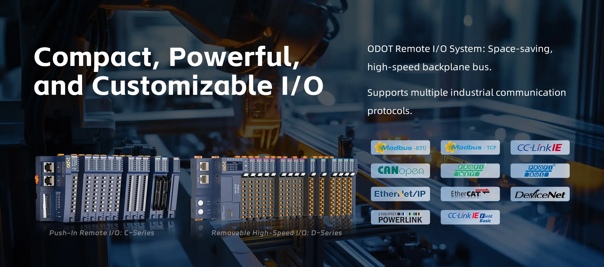
A Remote Io Coupler Adapter typically serves as the interface between a group of remote I/O modules and an industrial communication network. Depending on the product design, it may manage the station’s communication, identify connected modules, exchange process data, and provide diagnostic information. The precise functions vary by manufacturer, so engineers should check the adapter’s supported protocols, module family, and configuration requirements before designing the station.
The Coupler’s Place in a Distributed Station
A remote I/O station commonly consists of a network coupler or adapter and one or more I/O modules. The adapter connects the station to the controller network, while the modules handle the individual field signals.
For example, a station might contain digital input modules for switches, digital output modules for valve commands, and analog input modules for process transmitters. The coupler coordinates the data exchange between these modules and the controller.
This arrangement allows the station to be positioned near the equipment it serves. Local wiring terminates at the I/O modules, while a network cable connects the coupler to the wider automation system.
Protocol Compatibility Comes First
One of the most important selection criteria is communication compatibility. A coupler may support a particular industrial protocol, such as PROFINET, EtherCAT, or Modbus TCP. The controller and network architecture must support the same communication method or an appropriate integration mechanism.
Compatibility involves more than matching protocol names. Engineers should verify the supported device profile, configuration files, firmware requirements, data sizes, addressing method, and controller engineering environment.
If a gateway is used to connect different protocols, the project must account for data mapping, update intervals, diagnostics, and possible limitations in the information exchanged. A gateway should not be assumed to provide identical functionality to a native network connection.
Recognizing and Configuring I/O Modules
Many couplers work with a defined family of modules. The station configuration specifies which modules are installed and in what order. The controller uses this configuration to understand the structure of the remote I/O data.
An incorrect module order or configuration can prevent the station from starting correctly or cause the controller to interpret process data incorrectly. During commissioning, the installed hardware should be compared with the engineering configuration.
Some systems support automatic module identification, while others require the engineer to define the station manually. Even when identification is automatic, the configuration should be documented and verified.
Power and Electrical Requirements
The coupler and connected modules require suitable power. Depending on the architecture, logic power and field output power may be distributed separately. This separation can help prevent certain field-load problems from affecting the communication electronics, but the actual design depends on the product.
Engineers should calculate current consumption, verify supply voltage, consider voltage drop, and ensure that power distribution remains within the station’s limits. Output loads must be checked against module ratings, including inrush current where relevant.
The installation environment also matters. Temperature, vibration, moisture, dust, and electrical noise may influence where the station can be mounted and what enclosure protection is required.
Diagnostics and Fault Isolation
The coupler may provide status indicators or software diagnostics showing whether the station is communicating, whether modules are recognized, and whether certain faults have occurred. This can help technicians distinguish a network problem from a module or field wiring issue.
Troubleshooting should proceed systematically. Check the station’s power, network connection, device address or name, configuration, and module status. Then inspect the affected channel and field device.
Clear station labels and updated network drawings make fault identification faster. Replacement procedures should state whether the coupler requires configuration restoration or a controller download.
Planning for Maintenance and Expansion
Before choosing an adapter, consider the maximum number of supported modules, total process-data size, and options for adding future channels. A station that fits the initial signal list may become restrictive if the machine is expected to expand.
Spare couplers and modules should be selected from compatible product families. Firmware versions, configuration backups, and product lifecycle information should be recorded as part of the maintenance plan.
Conclusion
A remote I/O coupler adapter links distributed signal modules with the industrial network and helps organize communication between field devices and controllers. Selecting the correct adapter requires attention to protocol compatibility, module support, power requirements, configuration, and diagnostics. When these details are handled carefully, the coupler provides a dependable foundation for a well-structured remote I/O station.